You installed an electromagnetic flow meter to get accurate, hassle-free flow measurement:but now the display is blank, the reading is stuck at zero, or values keep jumping for no reason. It slows down plant operations, affects billing, and puts your PCB/PCB compliance reports at risk. When a flow meter misbehaves in an STP, ETP, water supply scheme, or process line, operators feel pressure from all sides: production, maintenance, and audits.
This expert guide on magnetic flow meter troubleshooting is designed to reduce that stress and give you a clear, step-by-step way to find the real cause of the problem and fix it safely. It explains the electromagnetic flow meter working principle in simple language so that even a non-instrumentation person can follow the logic.
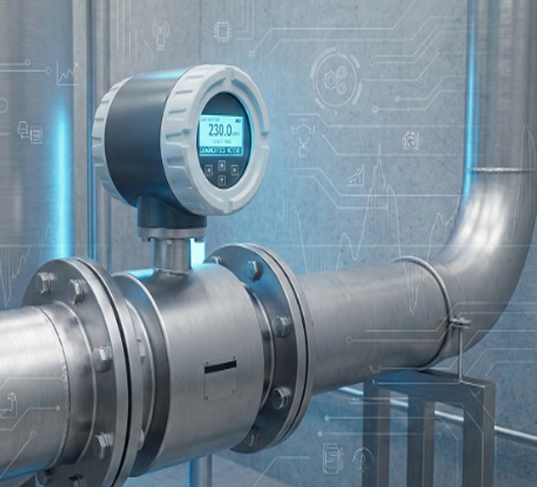
How an Electromagnetic Flow Meter Works
An electromagnetic flow meter uses Faraday’s Law of electromagnetic induction: when a conductive liquid moves through a magnetic field, a small voltage is generated across the fluid. That voltage is proportional to the velocity of the liquid and, with the known pipe size, converted into volumetric flow.
Key components that influence performance include:
- Electrodes: Sense the induced voltage in the fluid.
- Coil: Generates the magnetic field.
- Lining: Insulates and protects the meter body from process fluid.
- Transmitter: Converts the sensor signal into flow, totalizer, and outputs.
- Grounding: Provides a stable reference and reduces electrical noise.
Understanding this basic working principle helps during troubleshooting because most faults can be traced to issues that disturb the magnetic field, electrode signal, or reference to ground (for example, empty pipe, air, coating, wiring errors, or poor earthing).
Common Problems in Electromagnetic Flow Meters
In real plants, electromagnetic flow meters usually fail in a few predictable ways. Technicians often see:
- Zero reading despite confirmed flow in the pipeline.
- Incorrect or fluctuating readings, often without any obvious process change.
- Calibration drift over time, leading to mismatch with reference instruments.
- No output or no display from the transmitter.
- Communication issues on 4–20 mA loops or RS485 Modbus networks.
- Electrode coating, scaling, or sludge deposit.
- Grounding problems or electrical noise interference.
- Lining wear, damage, or chemical attack.
- Wrong installation location (too close to bends, valves, pumps, or air pockets).
Most issues are a combination of installation, process conditions, and maintenance gaps:not just “meter failure.” A structured approach avoids random trial-and-error and saves downtime.
How to Solve Flowmeter Problems
Follow these steps in order. Always follow your plant’s safety procedures and lockout/tagout rules whenever you open panels or remove instruments.
Step 1: Check Power Supply & Wiring
Start with basics. Confirm that the transmitter is powered with the correct voltage and frequency, and check fuses, MCBs, and terminals for loose or burnt connections.
For 4–20 mA loops, confirm polarity, loop power, and that the loop load (PLC, DCS, indicator) is wired correctly. For RS485 Modbus, verify A/B terminals, shielding, and that the communication ground is as per the manufacturer’s wiring diagram.
Step 2: Check Pipe Filling Condition
Electromagnetic flow meters need a full pipe to measure correctly. If the pipe is partially filled, has air pockets, or is at a high point, you will see erratic or low readings, or “empty pipe” alarms.
Visually confirm line conditions where possible, check upstream/downstream valves, and make sure the meter is not installed at the top of a vertical riser where air tends to accumulate.
Step 3: Inspect Grounding & Earthing
Good grounding stabilizes the signal and reduces interference. Check ground rings or grounding electrodes, continuity of grounding conductors, and earth resistance as per your plant standards.
Poor grounding can cause noisy, drifting, or unstable readings, especially in systems with variable frequency drives, welding machines, or heavy electrical loads nearby.
Step 4: Verify Installation Requirements (10D & 5D Rule)
The 10D/5D rule means having at least 10 pipe diameters (10D) of straight run upstream and 5D downstream of the flow meter. This helps flow become stable and reduces swirl from bends, valves, and pumps.
If the meter is installed too close to elbows, reducers, or control valves, the flow profile is distorted, leading to inaccurate or fluctuating readings. In severe cases, relocation or flow conditioners may be required.
Step 5 : Check for Electrode Coating or Scaling
Sludge, slurry, scale, high TDS deposits, or certain chemicals can coat the electrodes, increasing resistance and weakening the signal. This often leads to low readings, noisy output, or error codes related to electrodes.
Plan a safe shutdown, remove the sensor as per the manual, and clean the electrodes using an approved method and compatible cleaning agents. Avoid abrasives or sharp tools that may damage the lining or electrode surface.
Step 6 : Confirm Flow Direction & Sensor Orientation
Every EMF has a flow direction arrow. If the meter is installed opposite to the process flow, readings may be negative, incorrect, or unstable.
Also check that the sensor is installed so that electrodes are in a horizontal line, which helps avoid air bubbles sticking on electrodes.
Step 7 : Check Output Signal & Configuration
Use a multimeter to verify 4–20 mA output at the transmitter terminals and compare it with the displayed flow value and scaling. If no current is present with load removed, suspect configuration or internal faults. For RS485 Modbus, confirm device address, baud rate, parity, and mapping in the PLC/SCADA master. Many “communication faults” are simple parameter or wiring mismatches.
Step: 8 Verify Calibration and Zero-Setting
Magnetic flow meters do require calibration checks, especially in critical billing or compliance applications. Over time, drift, component ageing, or configuration changes can shift zero and span.
Factory calibration is done with specialized rigs and traceable standards, while on-site calibration and zero-setting help match the meter to actual process conditions. Plan periodic calibration based on your industry standards and audit needs.
Special Troubleshooting Scenarios
-
Flow Meter Not Reading Correctly
If readings are consistently off compared to a reference, look for air pockets, partially filled pipe, electrode fouling, and poor grounding.
Corrective actions include improving installation location, removing trapped air, cleaning electrodes, and checking configuration (pipe size, units, and scaling factors). -
Flow Meter Showing Zero Flow
When the display shows zero with confirmed flow, reasons often include electrical power issues, coil failure, empty pipe alarm status, or completely coated electrodes. - Check power, coils (as per manual), empty-pipe status, and electrode condition. If all external checks pass and the meter still shows zero, internal electronics may need factory inspection.
-
Fluctuating or Unstable Flow Reading
Fast fluctuations come from vibration, electrical noise, pulsing pumps, or unstable process flow.
Reduce vibration, check for nearby inverters or welders, improve grounding, and adjust damping or averaging settings in the transmitter so operators see a stable, usable value. -
How to Test an Electromagnetic Flow Meter
Basic testing includes simulating flow conditions, verifying the 4–20 mA output at different flow setpoints, checking diagnostics menus, and using built-in verification functions if available.
Some meters support internal simulation modes to test outputs without actual flow; others require a portable calibrator or comparison with a trusted reference meter. -
How to Check if a Flow Meter is Working
For operators, simple checks are: display health, alarm status, response to obvious flow changes (for example, closing/opening a valve), and output verification using a multimeter or SCADA trend.
If the meter responds logically to process changes and outputs are within expected range, it is generally considered healthy for day-to-day operation. -
How to Reset an Electromagnetic Flow Meter
A reset is useful when configuration is corrupted or the device is stuck. Many transmitters support soft reset (through menu) and hard reset (power cycle or factory default reset).
Before resetting, always record all configuration parameters, communication settings, and calibration data. After reset, re-enter parameters carefully and verify outputs and direction.
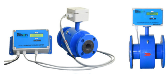
Manufacturer-Specific Notes (Bisan Focus)
Different branded meters may use different coil drive methods, diagnostics, and parameter structures, so their behavior under fault conditions can vary.
Using original spare parts, compatible linings, and recommended cables helps maintain accuracy and avoid unexpected errors or communication issues in the long run.
Bisan’s Full Bore and Insertion-Type electromagnetic flow meters are designed to minimize common failures with robust linings, stable electronics, and proven grounding and sealing practices. When combined with correct installation and regular checks, they provide stable, long-term performance in demanding ETPs, STPs, and process plants.
Preventive Maintenance Checklist
Use this practical checklist to reduce unplanned breakdowns:
- Monthly: Visual inspection of display, cables, glands, and junction boxes; check for error codes or unusual alarms on the transmitter.
- Quarterly: Verify 4–20 mA or communication values against SCADA, check grounding connections, inspect for vibrations or support issues around the meter location.
- Annual: Plan cleaning of electrodes (especially in slurry or high-TDS services), verify zero and span, and schedule calibration for critical billing or compliance meters.
- As needed: Sensor cleaning, lining inspection, and display diagnostics if process fluid or temperature conditions are severe.
When to Call a Professional Technician
Stop DIY troubleshooting and call an expert when you see repeated internal error codes, suspected coil or electronics failure, severe lining damage, or when the meter is part of a legal or billing measurement that must be certified.
Bisan Group offers support for installation, commissioning, calibration, and maintenance of electromagnetic flow meters so that plant teams can focus on operations while specialists handle complex diagnostics and repairs.
How Bisan Group Ensures Reliable Measurement
Bisan’s Full Bore meters cover a wide range of line sizes and are ideal for STP, ETP, water supply, and industrial process applications, while Insertion-Type meters are a cost-effective solution for large diameter pipelines.
Teflon and rubber lining options protect against corrosive and abrasive fluids, and LED/LCD transmitter options with advanced diagnostics make it easier for operators to identify issues early. PAN India support ensures quick response for both new installations and existing meter servicing.
Conclusion
Troubleshooting an electromagnetic flow meter becomes much simpler when you follow a clear sequence: check power and wiring, confirm full pipe and installation, verify grounding, inspect electrodes and lining, validate outputs and configuration, and then review calibration.
With proper installation, preventive maintenance, and timely expert support, your magnetic flow meter can deliver accurate, reliable flow data for years: which means smoother operations and easier PCB compliance.
FAQs
How to troubleshoot a magnetic flow meter?
Start by checking power, wiring, and grounding, then confirm full pipe conditions, correct installation lengths, electrode condition, and configuration parameters before considering internal faults or calibration issues.
How do I test if my electromagnetic flow meter is working?
Verify that the display and outputs respond to changes in flow, check 4–20 mA or Modbus signals with a meter or SCADA, and use any built-in test or simulation functions available in the transmitter.
Why is my flow meter not reading correctly?
Common causes include air in the line, partially filled pipe, electrode fouling, poor grounding, wrong installation location, or incorrect configuration such as pipe size or scaling.
Do magnetic flow meters require calibration?
Yes, they should be calibrated at the factory and then verified or recalibrated periodically depending on process criticality, regulatory requirements, and the manufacturer’s recommendations.
What are the common causes of flow meter errors?
Typical causes are installation errors, electrical noise, grounding issues, electrode coating, damaged lining, incorrect wiring, and changes in configuration or process conditions.
How do I reset an electromagnetic flow meter?
Use the menu for a soft reset or power cycle the instrument, and perform a factory-default reset only after recording all parameters so you can re-enter them correctly afterward.
What is the 10D/5D rule in electromagnetic flow meters?
It is a guideline to provide at least 10 diameters of straight pipe upstream and 5 diameters downstream of the meter, helping to ensure a stable flow profile and accurate measurement.